")


Meshes in 3D modeling are three-dimensional models composed of points, lines, and faces that allow for the creation of 3D objects and environments. 3D mesh files are used in many applications, including video games, animation, architecture, and product design. However, there are many different 3D mesh file formats, which can create interoperability problems between different software.
The native file format for 3DS Max is .max. While it is specific to 3DS Max, it is widely used in the 3D industry. It can store models, textures, lighting, animations, and special effects. However, the .max format is proprietary and cannot be opened by other 3D software. To share files with other professionals, it is recommended to export to a compatible format.
Collada (.dae) is an open and free 3D mesh file format that is supported by many 3D software applications, including 3DS Max, Blender, Maya, and Unity. It is used to store geometries, textures, animations, and special effects. Collada is considered a preferred 3D mesh file format for interoperability between different applications.
FBX (.fbx) is a proprietary 3D mesh file format developed by Autodesk. It is compatible with many 3D software applications, including 3DS Max, Maya, Blender, Unity, and Unreal Engine. FBX can store models, textures, lighting, animations, and special effects. It is often used in the video game industry for character assets and environments.
GlTF (.gltf) is a free and open 3D mesh file format developed by Khronos Group. It is designed to be used on the web and supports real-time broadcasting, virtual reality, and augmented reality. GlTF can store geometries, textures, animations, and special effects. It is supported by many 3D software applications, including Blender, 3DS Max, Maya, Unity, and Unreal Engine.
The native file format for LightWave is .lwo. It is used to store models, textures, lighting, animations, and special effects. Although this format is not as widely used as other 3D mesh file formats, it is supported by some 3D software, including 3DS Max.
OBJ (.obj) is an open and widely used 3D mesh file format for sharing 3D models. It can store geometries, textures, and materials. OBJ is supported by many 3D software applications.
OpenCTM (.ctm) is a free and open 3D mesh file format that is used to compress mesh data. It is designed to reduce the size of mesh files without losing visual quality. OpenCTM can store geometries, textures, and materials. It is supported by some 3D software, including Blender and OpenSceneGraph.
OpenSceneGraph (.osgt, .osgb) is a free and open 3D mesh file format that is used to create 3D visualization applications. It is used to store models, textures, lighting, and special effects. OpenSceneGraph is often used for simulation applications, architectural visualizations, and video games.
STL (.stl) is an open 3D mesh file format that is used for additive manufacturing, such as 3D printing. It stores geometries as a triangulated mesh. STL is supported by many 3D software applications, including 3DS Max and Blender.
USD (Universal Scene Description) is a free and open 3D mesh file format developed by Pixar. It is used to store complex 3D scenes including models, textures, lighting, animations and special effects. USD is designed to improve collaboration between artists, developers, and engineers in digital content production pipelines. It is supported by many 3D software including Maya, Houdini and Unreal Engine.
VRML (.wrl) is an open 3D mesh file format used to create virtual environments. It can store geometries, textures, lighting, animations, and special effects. VRML is often used for virtual reality applications and scientific visualization.
XGL (.xgl) is a proprietary 3D mesh file format developed by Softimage. It is used to store models, textures, lighting, animations, and special effects. Although not as widely used as other 3D mesh file formats, it is compatible with 3DS Max.
Virtual Reality Software Unreal Engine and Unity are two of the leading video game and virtual reality creation software available in the market today. Although both offer similar features, they each have their own advantages and disadvantages depending on the user's needs.
Unreal Engine is a game engine developed by Epic Games. It is known for its graphical power, ability to handle complex open worlds, and integration with cutting-edge technologies such as motion capture. Unreal Engine is also known for its use in AAA games and high-end virtual reality projects. However, its learning curve can be steep for beginners and it may require higher system resources.
On the other hand, Unity is a game engine that is also popular in the game and virtual reality development community. It is known for its ease of use, great flexibility, and extensive resource library, including tutorials and pre-made assets. Unity is often used for mobile games and medium-sized virtual reality projects. However, it is often criticized for its limitations in terms of graphics and performance.
In terms of interoperability for virtual reality, both software offer similar features for VR content creation. However, Unreal Engine is often preferred for high-end VR projects due to its graphical power and compatibility with third-party development tools. Unity, on the other hand, is often used for smaller VR projects and mobile virtual reality applications.
Contents
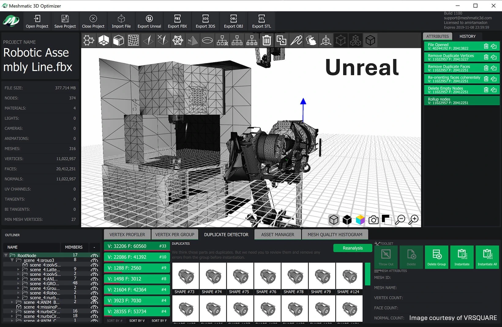
The manufacturing industry and architecture face a major challenge: effectively leveraging their complex CAD data in virtual reality and interactive visualization environments. Unreal Engine, initially designed as a video game engine, has now established itself as a platform of choice for industrial visualization, offering unmatched real-time rendering capabilities. However, transitioning precise CAD data to this visualization environment requires robust and optimized interoperability solutions.
The transition between traditional CAD systems and immersive environments like Unreal Engine poses several specific technical challenges: precise geometric conversion, assembly hierarchy management, preservation of important metadata, and optimization for real-time performance. These issues require specialized interoperability solutions that we will examine in detail.
Unreal Engine is a real-time interactive 3D content creation and exploitation software (RT3D) developed by Epic Games. Initially created as a video game engine and direct competitor to Unity, Unreal has gradually extended its application domain to industry and architecture.
Evolution of Interoperability Capabilities
Over the versions, the Unreal ecosystem has considerably expanded to meet the needs of industrial users:
This evolution reflects Epic Games' strategy to position Unreal as a reference solution for technical visualization and industrial virtual reality, well beyond its origins in the video game industry.
Unreal Engine offers different levels of extensibility for data interoperability, from the simplest to the most complex:
Datasmith represents the solution developed by Epic Games to facilitate the import of complex 3D data into Unreal Engine. This suite of tools enables the import of entire scenes potentially containing thousands of objects, each with its materials, pivots, scales, hierarchies, and metadata.
Main Capabilities of Datasmith:
Interchange Framework is the new generation of Unreal Engine's import/export infrastructure. This framework presents several distinctive advantages:
This modern approach will progressively replace older solutions and constitutes the future of interoperability in the Unreal ecosystem.
| Category | Format | Native Support | Via Datasmith (paid) | Import | Export |
|---|---|---|---|---|---|
| Standard Formats | FBX | ✓ | - | ✓ | ✓ |
| glTF | ✓ (experimental) | - | ✓ | - | |
| OBJ | ✓ | - | ✓ | - | |
| USD | ✓ | - | ✓ | ✓ | |
| CAD Formats | STEP | - | ✓ | ✓ | - |
| IGES | - | ✓ | ✓ | - | |
| JT Open | - | ✓ | ✓ | - | |
| Parasolid (x_t) | - | ✓ | ✓ | - | |
| 3DXML | - | ✓ | ✓ | - | |
| IFC | - | ✓ | ✓ | - | |
| Siemens PLM XML | - | ✓ | ✓ | - | |
| Specialized Formats | CATIA | - | ✓ | ✓ | - |
| NX | - | ✓ | ✓ | - | |
| SolidWorks | - | ✓ | ✓ | - | |
| Creo | - | ✓ | ✓ | - | |
| Revit | - | ✓ | ✓ | - | |
| Inventor | - | ✓ | ✓ | - |
Unreal Engine is capable of supporting various file formats for content import, but the FBX format stands out as a particularly effective solution for CAD interoperability. This section details the FBX import process and its capabilities to facilitate the transfer of 3D content to the Unreal environment.
The FBX (Filmbox) format is a flexible format owned by Autodesk that serves as a bridge between different digital content creation (DCC) applications. This universally recognized format offers several major advantages in the context of CAD interoperability:
Compatibility with Creation Tools
Some applications like Autodesk MotionBuilder natively support the format, while others like Autodesk Maya, Autodesk 3ds Max, and Blender support it via specific FBX plugins. This wide adoption makes FBX an ideal solution for exchanging technical data between heterogeneous environments.
Unreal Engine's FBX import pipeline supports a wide range of content and properties:
For Static Meshes:
For Skeletal Meshes:
Content import via the FBX pipeline follows a standardized process that allows for a smooth transition between creation environments and Unreal Engine:
A significant advantage of the FBX pipeline is its ability to transfer materials and textures applied to meshes from 3D applications to Unreal. This automated process significantly simplifies what was previously a manually intensive task.
Supported Material Types:
The FBX pipeline does not transfer all individual material parameters, but it supports the transfer of certain maps or textures used by materials. Commonly used textures are automatically connected to their default inputs on the material, but some will require manual connections.
For projects requiring the import of animations via FBX:
To maximize the quality and efficiency of data exchange via FBX, consider these best practices:
Using the FBX import pipeline in Unreal Engine represents a robust solution for CAD data interoperability, facilitating collaborative work between designers, engineers, and developers. This standardized approach allows for a smooth transition from virtually any 3D creation environment to Unreal's powerful real-time rendering engine.
CAD Interop offers several specialized solutions to optimize CAD data interoperability with Unreal Engine, addressing the needs for conversion, visualization, and simplification.
SimLab Composer is a powerful solution that provides a bridge between complex CAD data and Unreal Engine-based virtual reality environments.
Key Capabilities of SimLab Composer:
SimLab offers two main usage modes for VR integration with Unreal:
CADfix VIZ excels in optimizing CAD models for virtual reality, augmented reality, and mixed reality applications using Unreal Engine. This solution focuses on transforming complex 3D CAD assets into lightweight and performant meshes.
Main Features of CADfix VIZ:
CADfix VIZ supports a wide range of MCAD import formats, including CATIA, Creo, NX, SOLIDWORKS, STEP, and many others, ensuring maximum compatibility with existing design environments.
Preparing CAD data for Unreal Engine requires special attention to the following aspects:
For a better development experience with Unreal Engine in a CAD interoperability context:
| Feature | SimLab | Datasmith | Twinmotion |
|---|---|---|---|
| CAD Format Conversion | Extended support with structure preservation | Support via HOOPS Exchange | Support limited to standard formats |
| VR Interactivity | Complete real-time interactive experience | Requires import and configuration in Unreal | Primarily oriented towards 360° presentations |
| Visualization Autonomy | Creation of standalone executables (.VRpackage) | Requires Unreal Engine or packaging via UE | Export via Presenter |
| Model Optimization | Advanced simplification and optimization tools | Basic optimization features | Limited automated optimization |
| Collaborative Workflow | Support for teamwork and sharing | Integration with Unreal Collaboration | Limited sharing functions |
| Technical Support | Distributed and supported by CAD Interop | Support via Epic Games | Support via Epic Games |
| Ease of Use | Intuitive user interface, moderate learning curve | Requires knowledge of Unreal | Simplified interface, easy to learn |
Effective integration of CAD data into Unreal Engine opens up numerous possibilities for industrial companies:
The quality of interoperability directly determines the fidelity, performance, and efficiency of these critical applications.
The interoperability of CAD data with Unreal Engine represents a constantly evolving field, driven by technological innovations and the growing needs of industries. Solutions like SimLab Composer and CADfix VIZ distributed by CAD Interop offer specialized answers to the challenges of conversion, optimization, and visualization.
The future of this interoperability will be marked by several important trends, including cloud-based integration, increased automation of data preparation processes.
For companies seeking to fully exploit their CAD data in immersive environments, choosing an interoperability solution adapted to their specific needs constitutes a strategic decision that will directly influence the efficiency of their design, validation, and communication processes
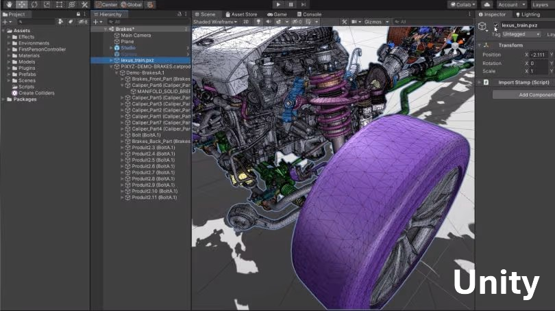
Table of Contents
CAD data interoperability with Unity represents a major challenge for industrial companies wanting to leverage their 3D models in virtual reality applications, interactive visualization, or training. The transition of complex CAD models to real-time environments like Unity poses numerous technical challenges: format conversion, geometry optimization, preservation of essential information, and performance management.
This guide explores the essential aspects of CAD-Unity interoperability: supported formats, available software solutions, best practices, and tips to optimize your workflows between your CAD systems and Unity.
Unity is software developed by Unity Technologies for the creation and utilization of interactive real-time 3D content (RT3D). Since its creation in 2005, this platform has evolved considerably to become a versatile tool beyond its initial domain of video games.
Although its adoption was initially concentrated in the fields of video games and cinema, Unity quickly found its place in industry and architecture for several professional applications:
Unity's constant evolution, with the addition of features like HDRP (High Definition Render Pipeline) and tools optimized for mobile devices and virtual reality, has considerably expanded its field of application in industrial environments.
Unity uses a geometric engine optimized for real-time rendering rather than for the precision of CAD models. This fundamental difference explains why direct import of CAD data into Unity often presents technical challenges.
Characteristics of Unity's geometric engine:
Unity imports 3D models through a processing chain based on the FBX format. This means that all other formats are first converted to FBX before being interpreted by the engine. This architecture explains why the FBX format is recommended as best practice for importing models into Unity.
Unity natively supports several standard and proprietary 3D formats. Here is a detailed table of supported formats:
| Format | Extension | Import | Export | Recommendations |
|---|---|---|---|---|
| Filmbox | .fbx | ✓ | ✓ | Preferred format, best compatibility |
| Wavefront | .obj | ✓ | ✓ | Good for simple geometries |
| COLLADA | .dae | ✓ | ✓ | Support for complex scenes |
| 3D Studio | .3ds | ✓ | ✗ | Limited to simple models |
| DXF | .dxf | ✓ | ✗ | Limited to simple 2D/3D models |
| Format | Extension | Import | Export | Notes |
|---|---|---|---|---|
| Autodesk Maya | .mb, .ma | ✓ | ✗ | Requires Maya installed on the workstation |
| Autodesk 3ds Max | .max | ✓ | ✗ | Requires 3ds Max installed on the workstation |
| Blender | .blend | ✓ | ✗ | Requires Blender installed on the workstation |
| Modo | .lxo | ✓ | ✗ | Requires Modo installed on the workstation |
| Cheetah3D | .jas | ✓ | ✗ | Requires Cheetah3D installed on the workstation |
| Format | Extension | Via paid plugins | Notes |
|---|---|---|---|
| STEP | .stp, .step | ✓ | Industrial standard format |
| IGES | .igs, .iges | ✓ | Old but widespread exchange format |
| Parasolid | .x_t, .x_b | ✓ | Format for volumetric models |
| CATIA V5 | .CATPart, .CATProduct | ✓ | Dassault proprietary formats |
| CATIA V6 | .3dxml | ✓ | Recent Dassault format |
| SolidWorks | .sldprt, .sldasm | ✓ | Dassault proprietary formats |
| NX | .prt | ✓ | Siemens proprietary format |
| Creo | .prt, .asm | ✓ | PTC proprietary format |
| JT | .jt | ✓ | Siemens visualization format |
| ACIS | .sat | ✓ | B-rep modeling format |
| Rhino | .3dm | ✓ | Format for NURBS surfaces |
It is important to note that importing native CAD formats into Unity generally requires specialized plugins or dedicated CAD-Unity solutions.
CAD Interop distributes several solutions to facilitate interoperability between CAD systems and Unity. These tools allow you to prepare, convert, visualize, and efficiently utilize CAD data in the Unity environment.
3DViewStation is a powerful and efficient CAD visualization solution that offers advanced features for analysis and interaction with 3D models. Its main features include:
This solution allows users to visualize and analyze CAD models before their integration into Unity, thus ensuring optimal data preparation for virtual reality applications.
SimLab is a complete solution for preparing virtual or augmented reality sessions from 3D models7. It offers:
SimLab greatly facilitates the transition from static CAD models to dynamic interactive experiences in Unity, without requiring in-depth development skills.
CADfix VIZ is a solution specialized in preparing CAD models for virtual reality and integration into Unity. Its key features include:
CADfix VIZ allows transforming complex CAD models into Unity assets optimized for real-time performance, while maintaining the necessary visual fidelity.
When it comes to preparing CAD models for Unity, several solutions are available on the market. Here is an objective comparison between CADfix VIZ and other commercial solutions:
| Feature | CADfix VIZ | Other solutions |
|---|---|---|
| Simplification algorithms | Advanced algorithms better preserving key characteristics | Good standard simplification algorithms |
| Geometry repair | Very advanced healing capabilities | Variable repair capabilities |
| Integration with Unity | External interface with import/export | Potentially better native integration in Unity |
| Supported formats | Wide range of CAD formats | Variable support depending on solutions |
| Structure preservation | Excellent preservation of assembly structures | Variable preservation of structures |
| Performance with very large models | Optimized for complex industrial models | Variable performance depending on solutions |
| Batch processing | Advanced | Variable depending on solutions |
CADfix VIZ particularly excels in the quality of simplification and geometric repair algorithms, which is crucial for maintaining the integrity of complex models while making them usable in Unity. However, some competing solutions may offer better direct integration into Unity, creating a more fluid workflow for regular users.
The choice between these solutions will mainly depend on your priorities: maximum geometric quality or fluid integration into the development environment.
To ensure optimal interoperability between your CAD systems and Unity, here are some essential best practices:
Here are some practical tips gathered from forums and the Unity community to improve CAD-Unity interoperability:
Interoperability between CAD systems and Unity represents a major technical challenge but opens up considerable possibilities for interactive visualization, virtual reality training, and virtual prototyping. The solutions distributed by CAD Interop such as 3DViewStation, SimLab, and CADfix VIZ offer complementary approaches to address these challenges.
The combination of appropriate tools, optimized exchange formats, and good model preparation practices allows establishing a smooth workflow between your CAD systems and the Unity environment. This efficient integration is essential to fully exploit the potential of virtual and augmented reality technologies in an industrial context.
Table of Contents
The STL (STereoLithography) format remains one of the most widely used standards for 3D data exchange in the manufacturing industry. Its simplicity and universal compatibility make it a pillar of CAD interoperability, but also pose significant technical challenges for engineers and designers. In an industrial environment where digital collaboration is essential, understanding the nuances of this format and mastering the tools to manipulate it effectively becomes a decisive competitive advantage.
The STL format, initially developed by 3D Systems in 1987, constitutes a simplified but effective representation of 3D geometries. Its name derives from "STereoLithography," referring to the first 3D printing technology for which it was designed.
The particularity of the STL format lies in its method of representing surfaces by tessellation:
The format exists in two main variants: ASCII and binary. The ASCII version, although human-readable, generates significantly larger files than its binary equivalent, the latter being preferred for industrial applications.
| Format | Characteristics | Advantages vs STL | Limitations vs STL |
|---|---|---|---|
| STL | Simple triangles | Universal standard | No color/texture |
| OBJ | Polygons, textures | Texture support | Increased complexity |
| PLY | Properties per vertex | Custom attributes | Less universal |
| 3MF | Modern format | Colors, materials, structures | Limited adoption still |
| STEP | Exact B-rep | Precise geometry | Complex conversion |
The STL format is distinguished by its mathematical simplicity, which facilitates data translation operations between heterogeneous systems while preserving the geometric essence of 3D models necessary for rapid prototyping and manufacturing.
CAD interoperability relies on the ability of exchange formats to maintain data integrity across different systems. The STL format, despite its popularity, presents several fundamental challenges that affect this capability.
The STL format suffers from technical constraints that complicate its use in advanced multi-CAD environments:
In modern digital chains, these limitations lead to practical complications:
The intrinsic simplification of the STL format creates obstacles for modern PLM systems:
These challenges require organizations to develop specific STL data management strategies to maintain information integrity throughout the product lifecycle.
The quality of an STL file essentially depends on the parameters used when exporting it from a native CAD system. Judicious choices allow for an optimal balance between geometric precision and file size.
Two fundamental parameters determine the quality of the STL mesh:
These parameters directly influence:
Recommendations by Application
| Application | Chordal Tolerance | Angular Tolerance | Specific Considerations |
|---|---|---|---|
| Visualization | 0.1-0.5 mm | 10-15° | Prioritize file lightness |
| Standard 3D Printing | 0.05-0.1 mm | 5-10° | Balance precision/weight |
| Precision Manufacturing | 0.01-0.03 mm | 1-5° | High fidelity required |
| Finite Element Analysis | 0.1-0.3 mm | 10-15° | Adaptation to critical areas |
| Virtual Reality | 0.2-0.5 mm | 10-20° | Optimization for performance |
A robust STL file validation process includes:
Adopting these best practices helps anticipate and resolve interoperability issues before they impact the digital value chain, thus ensuring smooth technical data exchanges between partners.
Facing the interoperability challenges of the STL format, specialized software solutions optimize the management, visualization, and conversion of data. CAD Interop offers a complete portfolio of professional tools addressing these specific needs.
3DViewStation offers a powerful solution for leveraging STL files in a business context:
This solution integrates perfectly into multi-CAD workflows by enabling rapid visual validation of STL models before their use in production.
For STL models with geometric imperfections, CADfix offers advanced healing functionalities:
CADfix distinguishes itself by its ability to transform problematic STL data into quality models, allowing their reintegration into demanding engineering processes.
SimLab transposes STL data into the dimension of virtual and augmented reality:
This innovative solution extends the use of STL data beyond the traditional technical domain, allowing marketing, training, and customer support teams to benefit from existing 3D models.
CAD Interop solutions integrate harmoniously into existing PLM environments:
This global approach allows overcoming the intrinsic limitations of the STL format while capitalizing on its simplicity and universality in technical data exchanges.
The STL format, despite its constraints, finds diverse applications in modern industry. Its judicious use, associated with appropriate tools, allows effectively solving specific CAD interoperability problems.
The historical application domain of STL remains additive manufacturing:
A European automotive supplier recently optimized its development process using 3DViewStation to validate and convert more than 5000 STL files monthly, reducing preparation time before printing by 40%.
The STL format often constitutes the first link in reverse engineering processes:
Successful integration of STL data into modern collaborative environments relies on:
The STL format also serves as an interface in simulation processes:
An aeronautical design office implemented a digital chain based on SimLab to visualize structural analysis results on STL models in virtual reality, significantly improving communication between technical teams and decision-makers.
CAD interoperability of the STL format remains a strategic issue for companies seeking to optimize their digital chains. While its simplicity constitutes both its strength and weakness, modern solutions allow transcending its intrinsic limitations.
The combination of specialized tools offered by CAD Interop - 3DViewStation for visualization and analysis, CADfix for repair and optimization, and SimLab for immersive experiences - offers a comprehensive approach to fully exploit the potential of STL data in demanding industrial environments.
To succeed in your STL-based interoperability strategy, we recommend:
By mastering these essential aspects, your organization can transform a simple geometric representation into a true digital asset, thus ensuring the continuity and efficiency of your engineering processes in an increasingly complex multi-CAD environment.
Table of Contents
In an industrial environment where 3D data circulates between different systems, departments, and partners, format interoperability becomes a crucial issue. The OBJ format, despite its longevity, remains an essential actor in the ecosystem of 3D visualization and technical data exchange. Its simplicity and universal compatibility make it a preferred choice for many applications, but its effective use requires a deep understanding of its characteristics and limitations.
The OBJ format has a rich history that explains its current position in the ecosystem of 3D formats.
The OBJ format, also known as Wavefront OBJ, was created in the 1980s by Wavefront Technologies for their flagship software, Advanced Visualizer. This software was a suite of applications dedicated to 3D animation, composed of specialized tools each targeting a specific task: modeling, animation, particle animation, etc.
Originally, OBJ primarily served to transfer data between different modules of the Advanced Visualizer software. After several mergers and acquisitions of Wavefront Technologies, the Advanced Visualizer software disappeared, but the OBJ format, being open and accessible, survived and became widely spread.
Its textual nature and simple structure greatly contributed to its widespread adoption. Unlike other proprietary formats of the time, OBJ could be easily analyzed and implemented by third-party developers, which accelerated its integration into many 3D software packages.
Today, OBJ has become a de facto standard format for 3D data exchange, used by both end users and in automated processing workflows. Its presence is particularly notable in:
This omnipresence testifies to the remarkable longevity of a format created more than four decades ago, a rarity in the constantly evolving technology industry.
The OBJ format is distinguished by a specific technical structure that defines both its strengths and limitations for CAD interoperability.
The OBJ format is essentially an ASCII text file, which makes it human-readable and modifiable using a simple text editor. This characteristic greatly facilitates debugging and manual modifications when necessary.
The structure of an OBJ file typically includes:
Although the OBJ format does not directly store color and texture information, it can define material properties via an associated MTL (Material Template Library) file. This complementary file contains specifications for:
The OBJ format primarily supports the polygonal representation of geometry. It can use:
This approach offers great flexibility for representing various shapes, but presents significant limitations for complex curved surfaces typical of CAD models.
The OBJ format generally uses two extensions:
Despite its versatility, the OBJ format presents several important technical limitations:
These technical characteristics define the optimal framework for using the OBJ format in CAD interoperability workflows.
Interoperability is an essential consideration when choosing a format for 3D data exchange. The OBJ format presents specific advantages and disadvantages compared to other major formats on the market.
Comparative Table: OBJ vs Major Formats for 3D Visualization and VR/AR
| Characteristics | OBJ | STL | glTF | FBX |
|---|---|---|---|---|
| Format Type | ASCII Text | Binary or ASCII | Binary or JSON | Proprietary Binary |
| Developer | Wavefront Technologies | 3D Systems | Khronos Group | Autodesk |
| Geometric Support | Polygons | Triangles only | Polygons and primitives | Polygons and NURBS |
| Textures | Via MTL file | Not supported | Integrated with PBR | Integrated |
| Materials | Basic via MTL | Not supported | Advanced PBR | Advanced |
| Animation | Not supported | Not supported | Supported (skeletons, morphs) | Supported (complete) |
| Metadata | Not supported | Not supported | Supported | Supported |
| Compression | Not supported | Not supported | Supported (Draco, etc.) | Supported |
| Main Usage | Static exchange, 3D printing | 3D printing | VR/AR, Web 3D | Animation, Cinema |
| File Size | Medium to large | Large for complex models | Optimized (small) | Large |
| VR/AR Integration | Limited | Very limited | Excellent | Good |
| Open Standard | Yes | Yes | Yes | No (proprietary) |
| Software Compatibility | Excellent | Excellent | Growing | Excellent |
OBJ vs STL for 3D Visualization
The comparison between OBJ and STL reveals significant differences:
OBJ vs glTF for Immersive Applications
The glTF format (GL Transmission Format), often called the "JPEG of 3D," presents several advantages over OBJ for VR/AR applications:
OBJ vs FBX for 3D Production
The FBX format, owned by Autodesk, is often compared to OBJ in production workflows:
How to Choose Between These Formats?
The choice of format essentially depends on the use case:
This comparative analysis allows strategically positioning the OBJ format in the 3D interoperability ecosystem and making informed choices according to the specific needs of each project.
CAD Interop offers several specialized solutions that support the OBJ format, each adapted to specific needs in the 3D data interoperability process.
SimLab Composer is a powerful solution distributed by CAD Interop that allows transforming OBJ models into immersive experiences.
SimLab Composer is particularly suited for professionals wishing to leverage their existing OBJ models for immersive commercial presentations, virtual reality training, or interactive design reviews.
3DViewStation is a high-performance 3D visualization solution distributed by CAD Interop that offers advanced functionalities for OBJ files.
3DViewStation is ideal for technical teams requiring rapid visualization and detailed analyses of OBJ models, as well as for departments that regularly need to convert data between OBJ and other CAD formats.
CADfix is a sophisticated solution distributed by CAD Interop, specialized in the repair and simplification of 3D models, including OBJ files.
CADfix is particularly useful for preparing complex or damaged OBJ models before their use in demanding applications such as simulation, manufacturing, or virtual reality.
These three solutions can be deployed individually or complementarily to create a complete OBJ file processing pipeline:
This integrated approach allows companies to maximize the value of their OBJ data while overcoming the inherent limitations of the format.
To make the most of the OBJ format in a collaborative environment, it is essential to adopt best practices that optimize interoperability and minimize potential problems.
Optimization of OBJ Files
The size and complexity of OBJ files can significantly impact performance. Here's how to optimize them effectively:
Naming and Organization Standards
Consistent organization facilitates the management of OBJ files:
Security and Sharing
Secure sharing of OBJ files, particularly in a professional context, requires precautions:
How to Manage OBJ Conversions in a Multi-CAD Environment?
Managing conversions to and from the OBJ format in a multi-CAD environment presents specific challenges:
Best Practices for Mobile Use
Using OBJ files on mobile devices requires particular considerations:
Adopting these best practices allows maximizing the efficiency of the OBJ format in enterprise workflows while minimizing potential problems related to its intrinsic limitations.
The OBJ format, despite its age and limitations, remains a pillar of 3D data interoperability in many industrial sectors. Its simplicity, open nature, and universal compatibility make it a relevant choice for many use cases, particularly when it comes to static visualization, basic geometry exchange, or 3D printing.
Nevertheless, the challenges inherent to the OBJ format - notably the lack of support for animation, metadata, and complex structures - require specialized solutions such as those offered by CAD Interop. SimLab, 3DViewStation, and CADfix offer complementary responses that allow overcoming these limitations and effectively integrating OBJ files into modern enterprise workflows.
The future of 3D interoperability is moving towards richer formats like glTF for immersive applications, but OBJ will likely continue to play an important role as a universal and accessible exchange format. The key to success lies in understanding the strengths and weaknesses of each format, combined with the use of appropriate tools to optimize conversions and exchanges.
By following the best practices presented in this document and leveraging specialized solutions, companies can build robust 3D data exchange pipelines where the OBJ format naturally finds its place among the broader ecosystem of CAD interoperability formats.
Table of Contents
Interoperability is a fundamental challenge for computer-aided design (CAD) professionals. In an environment where multi-platform collaboration has become essential, the glTF format (GL Transmission Format) has established itself as an effective solution for exchanging 3D models between different systems and software. Recognized for its lightweight nature and fast loading times, this format promotes fluid exchange of technical data while preserving the essential attributes of 3D models.
This open standard format addresses contemporary challenges in the manufacturing industry, particularly in contexts of rapid visualization, web integration, virtual and augmented reality, where data performance and fidelity are paramount. Its growing adoption demonstrates its relevance for CAD interoperability in an increasingly complex and heterogeneous digital ecosystem.
The glTF format originated in 2012, initially conceived as an evolution of the COLLADA format to meet the specific needs of WebGL. However, faced with technical constraints, the Khronos Group - a consortium of technology companies dedicated to open standards - chose to develop an entirely new format.
The first official specification, glTF 1.0, was published in 2015. This version laid the foundations for a format optimized for efficient transmission and rendering of 3D models. The following year marked a decisive turning point with the adoption of the format by major players such as Microsoft and Oculus, recognizing its potential to standardize 3D data exchanges.
Version 2.0, introduced later, significantly enriched the format's capabilities, notably with the integration of physically based rendering (PBR) and various improvements for compression and material management. This continuous evolution makes glTF an increasingly robust standard for 3D technical data interoperability.
The glTF format distinguishes itself through its design oriented toward transmission efficiency and performant rendering. Developed as a compact format that loads quickly, it particularly excels in applications requiring immediate display of 3D models.
Data Structure and Capabilities:
The versatility of the glTF format is manifested in its ability to maintain data integrity across different platforms while optimizing file size and rendering performance. Its modular architecture also allows the progressive integration of new functionalities via its extension system.
The glTF format comes in two main variants that address distinct interoperability needs:
Format .gltf (ASCII/JSON):
Format .glb (Binary):
This duality of formats offers valuable flexibility during the different phases of the CAD data lifecycle, from design to distribution.
The diversity of 3D data exchange formats can complicate technological choices for companies seeking to optimize their digital chain. To better position the glTF format within the ecosystem of exchange standards, it is essential to compare it with other major formats used in the industry. This objective comparison helps identify the relative strengths and weaknesses of each format according to specific interoperability needs.
The table below presents a detailed comparative analysis of the glTF format against three other significant exchange formats in the industry: JT, FBX, and OBJ.
| Characteristics | glTF | JT | FBX | OBJ |
|---|---|---|---|---|
| Full Name | Graphics Library Transmission Format | Jupiter Tessellation | Filmbox | Wavefront Object |
| Maintained by | Khronos Group | Siemens PLM | Autodesk | Community (historically Wavefront) |
| Year Created | 2015 | 1997 | 1996 | 1992 |
| Format | JSON (.gltf) or binary (.glb) | Binary | Proprietary binary | ASCII text |
| Standardization | Open format (Khronos standard) | ISO 14306 | Proprietary | De facto standard |
| File Size | Optimized (efficient compression) | Variable depending on compression | Medium to large | Large (uncompressed) |
| Main Use Cases | Web3D, AR/VR, lightweight visualization | Industrial CAD visualization, PMI | 3D production, animation, games | Simple geometric exchange |
| Geometric Representation | Optimized mesh, B-Rep via extensions | B-Rep, mesh, PMI | Detailed mesh | Mesh only |
| Material Support | PBR (Physically Based Rendering) | Basic to advanced | Complete and advanced | Basic (via MTL file) |
| Animation Support | Yes (skeletal and morph) | Yes | Yes (advanced) | No |
| PMI/Annotation Support | Via extensions | Native and complete | Limited | No |
| Compression | Draco (mesh), KTX (textures) | Multiple levels | Proprietary | No |
| Web Compatibility | Native (WebGL, WebGPU) | Limited | Limited | Medium (conversion needed) |
| PLM Integration | In development | Excellent | Limited | Weak |
| Main Advantages | Web performance, standardization, future-oriented | Industrial standard, feature-rich | Feature-rich, Autodesk ecosystem | Simplicity, universality |
| Main Disadvantages | CAD adoption in progress | Complexity, industrial specialization | Proprietary format, limited documentation | No animation, structural limitations |
Comparative Analysis:
The glTF format stands out for its optimization for web and mobile environments, offering an excellent compromise between visual quality and loading performance. Its modern design and extensible architecture make it a forward-looking solution for technical data interoperability, particularly in contexts of lightweight visualization and immersive experiences.
The JT format remains essential in demanding industrial environments, particularly for its native management of PMI (Product Manufacturing Information) and its deep integration with PLM systems. Its ISO standardization provides solidity for critical technical exchanges and long-term archiving.
The FBX format, owned by Autodesk, excels in animation and creative production domains, but its proprietary nature limits its use as an open interoperability standard. Its functional richness comes at the cost of increased complexity and dependence on the Autodesk ecosystem.
The OBJ format, a veteran of exchange formats, maintains its relevance thanks to its simplicity and universal support. However, its intrinsic limitations (absence of animation, basic structure) confine it to elementary geometric exchange uses without preservation of advanced attributes.
The glTF format is distinguished by its extensible architecture that allows enriching its basic functionalities to meet specific CAD interoperability needs:
Physically Based Rendering (PBR):
KTX 2.0 Texture Compression:
Draco Mesh Compression:
These extensions significantly increase the value of the glTF format for technical data exchange, combining visual fidelity, rendering performance, and file size optimization.
CAD Interop distributes several specialized solutions that leverage the capabilities of the glTF format for different phases of the CAD data lifecycle:
These complementary solutions cover all interoperability needs around the glTF format, from data preparation to their final use in specialized contexts.
Selecting the appropriate tool primarily depends on your interoperability objectives and the context of CAD data usage:
For quick consultation and validation:
For optimization of complex models:
For immersive applications:
Integrating these solutions into a coherent toolchain allows fully exploiting the potential of the glTF format for technical data interoperability.
To maximize the efficiency of interoperability with the glTF format, several practices recommended by domain experts deserve to be applied:
Geometry Optimization:
Efficient Texture Management:
Level of Detail (LOD) Implementation:
Multi-platform Validation:
Applying these best practices ensures smooth interoperability and optimal performance when using the glTF format in multi-platform CAD exchange contexts.
The glTF format is progressively establishing itself in various industrial sectors thanks to its versatility and efficiency for technical data interoperability:
Collaborative Design Review:
Interactive Technical Catalogs:
Assisted Training and Maintenance:
Cloud and Mobile Integration:
These concrete applications demonstrate how the glTF format transforms the way manufacturing companies exchange and exploit their CAD data across different departments and with their external partners.
The glTF format represents a significant advancement in addressing CAD data interoperability challenges in an increasingly digital and collaborative industrial ecosystem. Its performance-oriented design, extension flexibility, and growing adoption make it an essential standard for efficient transmission of 3D models between heterogeneous systems.
The solutions distributed by CAD Interop - 3DViewStation, CADfix, and SimLab - offer a complete set of tools allowing to fully exploit the potential of this format, from simple visualization to the creation of sophisticated immersive experiences, including optimization and repair of models.
Applying exchange and optimization best practices ensures optimal use of the glTF format in demanding industrial contexts. As standards evolve and capabilities enrich, glTF will continue to play a central role in the CAD interoperability ecosystem, facilitating collaboration between departments, companies, and industries.
To explore the possibilities of integrating the glTF format into your CAD interoperability strategy, don't hesitate to discover the specialized solutions offered by CAD Interop, designed to meet the specific needs of multi-CAD technical environments.
Table of Contents
In an industrial environment where communication between heterogeneous systems is becoming crucial, the FBX format has established itself as an essential solution for 3D data interoperability, particularly between CAD systems and advanced visualization applications. This versatile format allows crossing the technical barriers that often limit the fluid exchange of complex 3D models, thus facilitating collaboration between different departments and partners in the product development cycle.
The FBX (FilmBox) format was initially developed by the Canadian company Kaydara in the late 1990s. The founding objective was to create a universal format facilitating the exchange of 3D content between different platforms and applications.
Key historical milestones:
Over the years, Autodesk has considerably extended the capabilities of the format, transforming FBX from a simple exchange format into an industry standard for handling 3D data, animations, audio, and video. This evolution has been accompanied by increasing adoption in various industrial sectors, beyond its original domain of animation and visual effects.
The FBX format stands out for its ability to encapsulate a multitude of 3D information in a coherent and portable structure.
Main technical components:
The format exists in two main variants: binary (more compact) and ASCII (more readable and manually editable). Recent supported versions include versions 7.2, 7.4, and 7.5, each bringing improvements in terms of compatibility and functionality.
Storage capabilities:
This technical versatility makes FBX a format particularly suited to contexts requiring faithful transport of complex 3D data between different software environments.
The adoption of the FBX format in CAD workflows presents significant advantages, but also certain challenges to consider.
Main advantages:
These advantages make FBX a valuable ally for companies facing multi-CAD environments or seeking to leverage their technical data in advanced visualization contexts.
Challenges and limitations:
To address these challenges, Autodesk offers an SDK allowing developers to integrate support for the format into their applications, thus promoting its adoption in the industrial software ecosystem.
In the context of CAD data interoperability, the choice of exchange format is crucial to ensure data integrity and optimize workflows. The FBX (FilmBox) format occupies an important place in the ecosystem of 3D formats, but how does it compare to other major formats on the market? This comparative analysis will help you make the most suitable choice for your needs.
| Characteristic | FBX | glTF | OBJ | USD |
|---|---|---|---|---|
| Developer | Autodesk | Khronos Group | Wavefront Technologies | Pixar |
| File type | Binary/ASCII | Binary/JSON | ASCII | Binary |
| Main usage | Animation, video games, VFX | Web, AR/VR | Static models | Complex scenes |
| Year of origin | 1996 (Kaydara) | 2016 | 1980s | 2012 |
| Animation support | Excellent | Good | Not supported | Excellent |
| Texture support | Complete | Good | Basic | Very advanced |
| File size | Medium to large | Compact | Medium | Large |
| Key advantages | Richness of scene data, preservation of hierarchies | Web efficiency, optimized size | Simple, universally supported | Collaboration, advanced scene management |
| Limitations | Proprietary, complex format | Limited material complexity | No animation, geometry only | Complex implementation |
| Software compatibility | High | Moderate to high | Very high | Growing |
| Ideal use case | Multimedia production, transfer between creation software | Web and mobile applications | Simple geometry exchange | Film production, complex scenes |
This comparison highlights the strengths and weaknesses of each format in the context of CAD interoperability. The choice of format will largely depend on your specific objectives and software ecosystem.
CAD Interop offers several specialized solutions to fully exploit the potential of the FBX format in your engineering and design workflows.
3DViewStation constitutes a powerful solution for the visualization and analysis of FBX models, also offering conversion capabilities to and from this strategic format.
Key features:
CADfix presents itself as a complete solution for the translation, repair, healing, and simplification of CAD models, including files in FBX format.
Main capabilities:
SimLab Studio allows you to transform your FBX models into immersive virtual reality experiences, without requiring programming skills.
Distinctive characteristics:
Together, these solutions form a complete ecosystem allowing you to fully exploit the potential of the FBX format at each stage of your digital workflow.
Effective integration of the FBX format into your existing processes requires a methodical approach and some best practices.
Optimization strategies:
Typical workflow for VR data preparation:
This structured approach ensures a smooth transition of technical data to advanced visualization applications, thus maximizing the value of your digital assets.
How to ensure maximum quality when converting to FBX?
To obtain the best results when exporting to FBX, prefer recent versions of the format (7.4 or 7.5), check export parameters concerning normals and UVs, and always perform a visual check post-conversion to validate the integrity of the model.
What are the limitations to be aware of regarding animations in FBX?
Although FBX excels in transferring animations, certain constraints exist, particularly regarding complex physical simulations or non-linear deformations. It is recommended to simplify critical animations and to thoroughly test their behavior after conversion.
How to effectively manage textures with the FBX format?
For optimal texture management, prefer the option to embed textures in the FBX file during export or maintain a coherent folder structure. Use standard image formats such as PNG or JPG, and check UV mapping parameters to avoid distortions.
Why do some elements disappear during conversion to FBX?
The disappearance of elements may result from unsupported geometries, names containing special characters, or attributes specific to the source system. Use tools like CADfix to identify and resolve these issues before the final conversion.
How to integrate FBX into a long-term archiving strategy?
Although FBX is widely adopted, it remains a proprietary format. For long-term archiving, consider a hybrid strategy combining FBX with standardized formats such as STEP or JT, accompanied by detailed documentation of the conversion processes.
By following these recommendations and leveraging CAD Interop's specialized solutions, you can fully benefit from the FBX format to improve the interoperability of your technical data and enrich your product development processes.
Table des matières
Dans l'écosystème complexe des formats de données 3D, l'interopérabilité demeure un défi majeur pour les professionnels manipulant différents logiciels de CAO. Le format COLLADA (COLLAborative Design Activity) représente une solution standardisée facilitant l'échange de données 3D entre applications hétérogènes, permettant aux ingénieurs et concepteurs de partager efficacement leurs modèles numériques indépendamment des plateformes logicielles utilisées.
COLLADA se présente comme un format d'échange de fichiers XML open source destiné aux applications 3D interactive. Sa mission fondamentale est de briser les barrières techniques entre différents logiciels de création graphique, offrant ainsi une solution d'interopérabilité standardisée pour l'industrie. En tant que format adopté par l'ISO sous la spécification ISO/PAS 17506, COLLADA occupe une position stratégique dans l'écosystème des technologies de visualisation et de réalité virtuelle.
Les documents COLLADA qui décrivent les actifs numériques sont des fichiers XML identifiés par l'extension .dae (digital asset exchange), facilitant leur reconnaissance et leur traitement par divers systèmes.
Le format COLLADA a été initialement développé chez Sony Computer Entertainment par Rémi Arnaud et Mark C. Barnes pour répondre aux problèmes d'interopérabilité rencontrés dans l'industrie du jeu vidéo et de la 3D. Ce format est ensuite devenu la propriété du Khronos Group, un consortium technologique à but non lucratif qui partage désormais les droits d'auteur avec Sony.
Dès ses débuts, plusieurs entreprises majeures de l'industrie graphique ont collaboré avec Sony pour créer un outil qui serait utile au plus grand nombre, notamment :
Cette collaboration précoce a permis au format de bénéficier d'une vision diversifiée, répondant aux besoins de multiples secteurs industriels.
L'évolution du format COLLADA s'est caractérisée par plusieurs jalons importants :
Grâce à ces développements, COLLADA a progressivement gagné en adoption dans diverses industries, notamment les studios de jeux vidéo et les moteurs de jeu qui ont intégré ce standard dans leurs flux de travail.
COLLADA se distingue par sa structure basée sur le schéma XML, qui facilite l'échange d'actifs numériques entre diverses applications graphiques tout en maintenant l'intégrité des données et la cohérence visuelle.
Le format COLLADA se présente principalement sous deux formes :
COLLADA permet aux créateurs de contenu de définir diverses caractéristiques physiques dans les scènes visuelles, incluant :
La version 1.4 du format a notamment ajouté le support de la physique, permettant aux différents outils et middleware d'échanger des données physiques de manière standardisée, contribuant à l'enrichissement des simulations et des environnements virtuels.
COLLADA joue un rôle crucial dans les flux de travail d'interopérabilité CAO en facilitant le transfert de données 3D entre différentes applications logicielles. En tant que format intermédiaire, il permet de rediriger les informations 3D d'un logiciel à un autre, surmontant ainsi les limitations des formats propriétaires fermés.
Ce format a été conçu comme un standard d'échange pour permettre aux actifs 3D d'être partagés entre diverses applications graphiques qui pourraient autrement stocker leurs données dans des formats de fichiers incompatibles. Cette capacité est particulièrement précieuse dans les environnements de travail multi-logiciels.
Dans le domaine de la CAO et de la visualisation 3D, COLLADA est supporté par de nombreux logiciels populaires :
Le format COLLADA a trouvé des applications particulières dans plusieurs secteurs :
Malgré ces avantages, il convient de noter que la spécification de fichier COLLADA n'est pas très stricte, ce qui peut occasionnellement générer des problèmes d'interopérabilité entre les exportations COLLADA provenant de différents logiciels. Cette particularité peut nécessiter une attention supplémentaire lors de l'établissement de flux de travail inter-logiciels.
Le format COLLADA s'est imposé comme une solution particulièrement adaptée aux applications de visualisation 3D et de réalité virtuelle, offrant des capacités étendues pour la création d'expériences immersives.
COLLADA est largement utilisé pour la visualisation d'environnements architecturaux et urbains. Il permet :
Dans le domaine de la réalité virtuelle, COLLADA offre la possibilité d'intégrer divers attributs essentiels pour créer des expériences véritablement immersives :
Ces capacités font de COLLADA un format particulièrement approprié pour les applications VR nécessitant un haut niveau de fidélité sensorielle.
Le support de la physique dans COLLADA a été adopté par plusieurs produits middleware, permettant des simulations réalistes :
Ces produits peuvent interpréter l'abstraction contenue dans le fichier COLLADA et la transférer dans une forme que le middleware peut supporter et représenter dans une simulation physique, permettant ainsi des interactions réalistes dans les environnements virtuels.
COLLADA s'adapte également aux applications graphiques 3D mobiles, particulièrement celles utilisant des interfaces tactiles. Des balises XML spécifiques peuvent être utilisées pour représenter les valeurs de poids des objets 3D, déterminant comment l'interface tactile fonctionne pour déplacer ces objets en fonction de leur poids, créant ainsi des interactions plus naturelles et intuitives.
CAD Interop distribue plusieurs solutions logicielles performantes pour la préparation, la visualisation et la conversion des fichiers COLLADA. Ces outils sont essentiels pour maximiser les avantages de l'interopérabilité offerts par le format COLLADA dans les flux de travail CAO professionnels.
3DViewStation est une solution puissante pour visualiser et analyser des modèles COLLADA, ainsi que pour convertir vers et depuis le format COLLADA à partir d'autres formats CAO. Ses fonctionnalités principales incluent :
3DViewStation permet aux professionnels de l'ingénierie de travailler efficacement avec des fichiers COLLADA dans leurs flux de travail quotidiens, améliorant l'interopérabilité entre différents systèmes CAO et assurant l'intégrité des données lors des conversions.
SimLab se positionne comme une solution spécialisée pour la création d'expériences immersives à partir de fichiers au format COLLADA. Particulièrement adaptée aux applications de réalité virtuelle et de visualisation interactive, cette suite d'outils offre :
SimLab Collada Exporter est notamment disponible pour Autodesk Revit, permettant d'exporter directement les conceptions Revit vers des fichiers COLLADA depuis l'environnement Revit, avec une préservation optimale de la structure et des matériaux.
Ces solutions distribuées par CAD Interop offrent une réponse complète aux besoins de translation de données, de healing géométrique et de model-based definition (MBD) dans un contexte d'interopérabilité multi-CAO.
Pour maximiser l'efficacité de l'interopérabilité lors de l'utilisation du format COLLADA, il est recommandé de suivre plusieurs bonnes pratiques issues de l'expérience des utilisateurs professionnels.
Il est vivement conseillé de valider systématiquement les fichiers COLLADA avant leur importation dans d'autres applications :
Pour améliorer la qualité et les performances des modèles importés :
Une organisation claire du modèle facilite son traitement ultérieur :
Pour assurer une représentation fidèle des modèles 3D :
Pour les applications de réalité virtuelle et de visualisation immersive :
Ces bonnes pratiques, combinées aux capacités des solutions distribuées par CAD Interop, permettent d'exploiter pleinement le potentiel du format COLLADA dans les environnements professionnels d'ingénierie et de création numérique.
Le format COLLADA continue de jouer un rôle important dans l'écosystème de l'interopérabilité CAO, particulièrement pour les applications de visualisation et de réalité virtuelle. Malgré l'émergence de formats plus récents comme glTF (recommandé par ArcGIS CityEngine comme alternative pour certains cas d'usage), COLLADA maintient sa pertinence grâce à sa large adoption et son support par de nombreux logiciels et outils.
Les solutions proposées par CAD Interop, notamment 3DViewStation et SimLab, offrent des moyens efficaces pour travailler avec le format COLLADA, que ce soit pour la visualisation, l'analyse ou la création d'expériences immersives. En suivant les bonnes pratiques d'échange de fichiers COLLADA, les professionnels peuvent maximiser les avantages de l'interopérabilité tout en minimisant les problèmes potentiels.
L'avenir du format COLLADA s'oriente vers :
Dans un contexte où la collaboration numérique et l'échange de données 3D sont essentiels, le format COLLADA, soutenu par des solutions performantes comme celles distribuées par CAD Interop, demeure un outil précieux pour surmonter les barrières technologiques et faciliter la communication entre différentes plateformes logicielles dans l'écosystème de conception assistée par ordinateur.
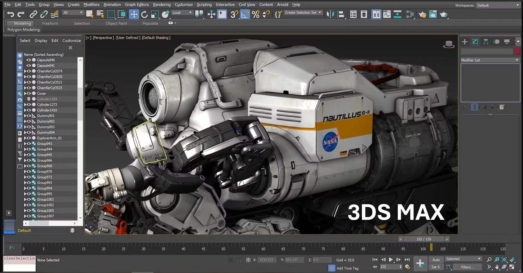
Table of contents
CAD data interoperability represents a crucial issue for professionals in 3D modeling, animation, rendering, and visualization. Autodesk 3DS MAX, one of the most popular software in these fields, offers numerous possibilities for data exchange with other applications. Its ability to import and export a wide variety of formats makes it a central tool in modern 3D production pipelines, facilitating collaboration between different teams and software.
Autodesk 3DS MAX finds its origins in initial development by the Yoast Group in 1988. Initially launched under the name 3D Studio in 1990 for MS-DOS, the software underwent a major evolution in 1996 with its Windows version, called 3D Studio Max.
In 1999, Autodesk acquired 3D Studio and renamed it 3D Studio MAX, marking a decisive turning point in the software's history4. This acquisition allowed for greater investment of resources to transform the tool into a complete 3D modeling, animation, and rendering solution.
Over the years, 3DS MAX quickly established itself in the fields of video games and cinema, supported by a dynamic community of developers and users3. The progressive integration of tools for architects has also expanded its audience to construction professionals and architectural visualization.
Today, the software continues to evolve and remains an essential reference in the industry, often described as the "Swiss Army knife of 3D" due to its exceptional versatility.
3DS MAX distinguishes itself by its exceptional ability to support a wide range of file formats, making it a central tool for 3D data interoperability.
| Category | Format | Extension | Import | Export |
|---|---|---|---|---|
| Autodesk Formats | FBX | .FBX | ✓ | ✓ |
| 3D Studio Mesh | .3DS, .PRJ | ✓ | ✓ | |
| AutoCAD | .DWG | ✓ | ✓ | |
| Inventor | .IPT, .IAM | ✓ | ✗ | |
| Revit | .RVT | ✓ | ✗ | |
| Alias | .WIRE | ✓ | ✗ | |
| CAD/CAM | CATIA V5 | .CATPART, .CATPRODUCT, .CGR | ✓ | ✗ |
| CATIA V4 | .MODEL, .MDL, .SESSION, .EXP, .DLV | ✓ | ✗ | |
| IGES | .IGE, .IGS, .IGES | ✓ | ✓ | |
| JT | .JT | ✓ | ✗ | |
| NX | .PRT | ✓ | ✗ | |
| Creo | .PRT, .NEU, .G, .ASM | ✓ | ✗ | |
| SolidWorks | .SLDPRT, .SLDASM | ✓ | ✗ | |
| STEP | .STP, .STEP | ✓ | ✓ | |
| ACIS | .SAT | ✓ | ✓ | |
| 3D Standards | Alembic | .ABC | ✓ | ✓ |
| Collada | .DAE | ✓ | ✓ | |
| OBJ | .OBJ | ✓ | ✓ | |
| STL | .STL | ✓ | ✓ | |
| Universal Scene Description | .USD, .USDA, .USDC | ✓ | ✓ | |
| VRML | .WRL, .WRZ | ✓ | ✓ |
The native format of 3DS MAX (.MAX) plays an essential role in its interoperability ecosystem6. This format constitutes a complete scene containing all components and references to content, including:
This format is particularly valuable for complex projects involving numerous files and external references, greatly facilitating collaboration between different team members6.
The .3DS format is one of the file formats supported by 3DS MAX6. This format was the native format of the old version of Autodesk 3D Studio and has become a de facto standard for transferring models between different 3D software. Although more limited than the .MAX format, the .3DS format preserves essential information:
FBX (Filmbox) technology constitutes the cornerstone of interoperability in the Autodesk ecosystem. This universal format facilitates the exchange of complex 3D data between different digital creation applications.
FBX preserves the essential elements during transfer between applications:
FBX serves as a pivot format for bidirectional exchanges between 3DS MAX and other applications in the Autodesk suite, notably Maya and MotionBuilder. This interoperability allows production teams to:
Since 2019, the optimization of BIM workflows increasingly goes through 3DS MAX rather than directly via Revit. This approach offers significant advantages:
The Revit-3DS MAX workflow enables the establishment of an efficient BIM-to-Visualization pipeline where technical data is transformed into convincing visualizations without compromising on quality or accuracy.
One of the major assets of 3DS MAX in the BIM context is its ability to preserve IFC data and technical metadata when importing Revit models. This functionality is crucial for the AEC (Architecture, Engineering, Construction) industry, allowing the preservation of:
CAD Interop distributes several powerful solutions to optimize the interoperability of 3DS MAX data.
3DViewStation offers a complete solution for the visualization and analysis of 3DS MAX models without requiring the original software:
SimLab transforms 3DS MAX models into immersive and interactive experiences, ideal for presenting architectural or product projects:
CADfix is a specialized solution for the repair and simplification of CAD data from 3DS MAX:
To optimize the interoperability of 3DS MAX data, here are some essential recommendations:
How to preserve animations when exporting to other applications?
To preserve animations, use the FBX format which supports animation curves, skeletons, and skinning. Make sure to check the appropriate options in the FBX export dialog, particularly "Animation", "Deformations", and "Bake Animation".
Is it possible to import parametric CAD models into 3DS MAX?
No, 3DS MAX can't import parametric models from software such as CATIA, SolidWorks, or Inventor. These models are generally converted to meshes or NURBS geometries, thus losing their parameterization.
How to optimize 3DS MAX models for game engines?
For game engines, export in FBX with optimized meshes, power-of-2 format textures, and fixed-rate animations. Limit material complexity and use normal maps rather than detailed geometries for small elements.
What is the best approach for exchanging data between 3DS MAX and CAD software?
For exchange with CAD software, favor neutral formats like STEP or IGES which better preserve geometric precision. For more specific exchanges, dedicated converters like those distributed by CAD Interop offer superior results in terms of fidelity and data preservation.
CAD data interoperability with 3DS MAX constitutes a crucial element for modern collaborative workflows. Thanks to its extensive support of import/export formats, its deep integration with the Autodesk ecosystem via FBX, and specialized solutions like those offered by CAD Interop, 3DS MAX establishes itself as an essential link in the 3D production chain, whether for animation, architecture, video games, or industrial visualization.
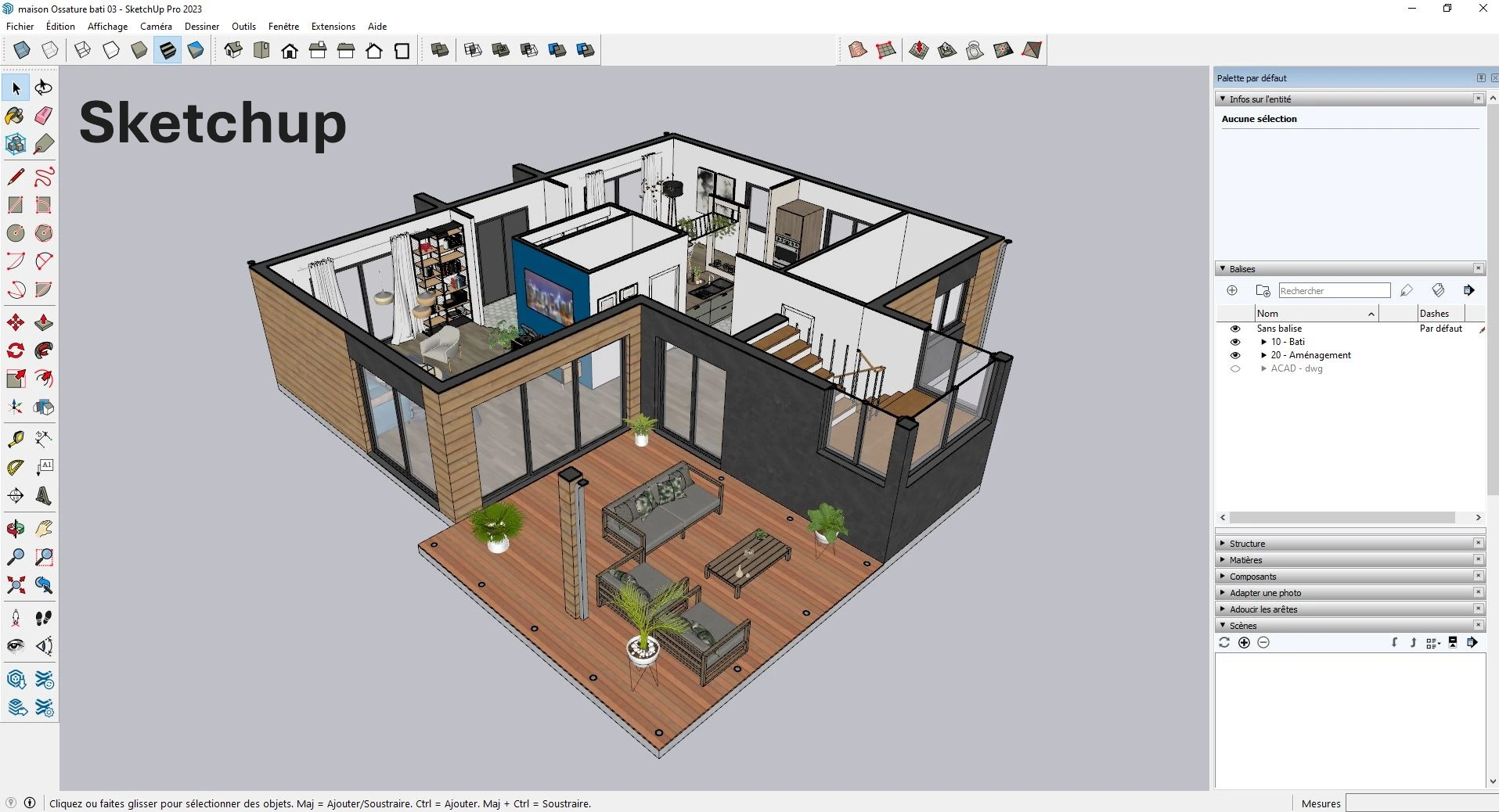
Table of Contents
Technical data interoperability is a major challenge for companies using SketchUp in their design and production workflows. In a complex multi-CAD environment, the ability to exchange 3D and 2D models without loss of information becomes a determining factor of productivity. This article explores solutions and strategies to maximize interoperability between SketchUp and other CAD systems, ensuring reliable and efficient data conversion.
SketchUp has undergone a remarkable evolution since its creation, shaping its current position in the CAD interoperability ecosystem.
The origins (1999-2006)
SketchUp was initially developed by @Last Software, founded in 1999 by Brad Schell and Joe Esch in Boulder, Colorado. The founding principle was to create 3D software that was easy to learn and use - "3D for everyone". The first official version was launched in August 2000, immediately winning the "Best New Products or Services" award at the A/E/C SYSTEMS Fall 2000 exhibition.
The Google era (2006-2012)
The growing popularity of SketchUp attracted Google's attention, which acquired @Last Software in March 2006. This acquisition followed a fruitful partnership around Google Earth, allowing users to model buildings for this platform. Under Google's aegis, SketchUp became democratized with two versions:
The Trimble era (2012-present)
In 2012, Google transferred SketchUp to Trimble, a company specializing in the BIM industry. Under Trimble, the software continued to evolve with significant improvements in interoperability and regular annual updates that have continued to this day.
This evolution has allowed SketchUp to become a central tool in many sectors, from architecture to game design, including performing arts and design.
SketchUp's geometric engine stands out for its unique approach to 3D modeling, favoring simplicity while offering considerable power for technical data exchange.
Architecture of the modeling engine
SketchUp uses an edge-face modeling system, different from the more complex B-rep (Boundary Representation) systems used by other CAD software. This approach allows direct and intuitive manipulation of geometries while maintaining a lightweight data structure.
Supported geometric elements
The SketchUp engine efficiently manages:
Geometric healing capabilities
When importing CAD files, SketchUp offers options to improve the quality of geometries:
These features are essential when translating data between different CAD systems, particularly between native and neutral formats. For complex files, this healing capability significantly contributes to the quality of imported models and their subsequent usability.
One of SketchUp's strengths lies in its ability to communicate with different CAD systems via a wide range of file formats. Understanding these formats is essential for effective CAD interoperability.
Table of formats supported by SketchUp
| Category | Format | Extension | Import | Export | Availability |
|---|---|---|---|---|---|
| Native formats | SketchUp | .skp | ✓ | ✓ | All versions |
| DAO/CAD formats | AutoCAD | .dwg | ✓ | ✓ | Pro only |
| AutoCAD | .dxf | ✓ | ✓ | Pro only | |
| Exchange standards | IFC | .ifc | ✓ | ✓ | Pro/Studio (improved in 2025) |
| STEP | .step, .stp | × | × | Via extensions | |
| IGES | .igs, .iges | × | × | Via extensions | |
| 3D formats | Collada | .dae | ✓ | ✓ | All versions |
| 3D Studio | .3ds | ✓ | ✓ | Pro only | |
| OBJ | .obj | ✓ | ✓ | Pro only | |
| FBX | .fbx | ✓ | ✓ | Pro only | |
| VRML | .wrl | × | ✓ | Pro only | |
| 2D formats | × | ✓ | Pro only | ||
| EPS | .eps | × | ✓ | Pro only | |
| Image | .jpg, .png, .tif | ✓ | ✓ | All versions | |
| Point clouds | LAS | .las | ✓ | × | Pro/Studio |
| LAZ | .laz | ✓ | × | Pro/Studio | |
| BIM | Revit | .rvt | ✓* | × | Studio only |
*Requires the Revit importer available only with Studio subscription
Latest interoperability improvements
The 2025 version of SketchUp significantly strengthens interoperability capabilities with:
These improvements address the growing need for reliable data exchange in multi-CAD projects and collaborative environments.
The efficiency of a multi-CAD workflow heavily depends on the quality of exchanges between SketchUp and other computer-aided design systems. This section explores the specifics of these interactions.
SketchUp Pro allows importing and exporting AutoCAD files in DWG and DXF formats7. When importing, SketchUp supports many entities:
However, some entities are not supported:
For export, SketchUp offers two distinct options:
For SketchUp Studio subscribers, direct import of Revit files (.rvt) is possible via a dedicated tool that:
For users without the Studio subscription, other exchange methods exist such as IFC export or the use of intermediate formats.
The IFC format (Industry Foundation Classes) plays a crucial role in BIM interoperability. The latest version of SketchUp has significantly improved its support:
These exchange standards greatly facilitate geometric validation and PLM integration in multi-CAD enterprise projects.
SimLab Composer represents a powerful solution distributed by CAD Interop to extend SketchUp's interoperability capabilities towards immersive experiences and advanced visualizations.
SimLab Composer integrates with SketchUp via a free plug-in that creates an active link between the two applications8. This bidirectional connection allows:
SimLab Composer enriches SketchUp models with:
This plugin works with the latest versions of SketchUp on Windows and macOS, offering a cloud-based collaboration solution accessible regardless of the work environment.
SimLab Composer thus transforms SketchUp models into powerful and interactive technical communication tools, particularly useful for:
This solution complements the SketchUp ecosystem by offering advanced Model-based definition (MBD) capabilities while preserving the integrity of the original technical data.
Effective exchange of SketchUp models with other CAD systems requires careful preparation and adherence to certain fundamental principles. Here are the best practices to ensure quality CAD interoperability.
To optimize your SketchUp models before export:
When importing DWG or DXF files:
For conversions between SketchUp and other formats:
These best practices significantly contribute to the quality of exchanged data and the reduction of time spent on model rework after conversion.
In a distributed work context, technical data exchange goes beyond simple format interoperability. It becomes essential to establish effective collaboration processes around SketchUp models.
Trimble Connect offers a robust cloud solution for sharing and collaborating around SketchUp models:
For effective collaboration on multi-CAD projects:
For complex technical projects:
These collaborative approaches significantly strengthen the efficiency of technical data exchanges, particularly important in projects involving multiple companies and different CAD systems. The centralization of exchanges also contributes to long-term data archiving and their subsequent retrieval.
In an environment where multiple CAD systems coexist, optimizing interoperability becomes a technical challenge. This section presents strategies and solutions truly compatible with SketchUp to maximize the efficiency of data exchanges.
For complex professional environments, several extensions extend native interoperability capabilities:
For specific sector needs:
The latest versions of SketchUp offer significantly improved IFC capabilities:
To establish a robust interoperability strategy:
The adoption of these compatible solutions transforms CAD interoperability from a technical challenge into a strategic advantage, facilitating multi-CAD collaboration in complex projects and significantly reducing the risk of errors in data translation
Paris, Wednesday, April 2, 2025, We are pleased to present the latest update from KISTERS, 3DViewStation 2025.1.187, available today. This version consolidates and optimizes the revolutionary features introduced in version 2025.0 launched last March, while bringing targeted improvements to meet the needs of industry professionals.
The latest release of DEXcenter, now available on AWS Marketplace, transforms how professionals automate CAD data exchanges with enterprise-grade security. Developed by ITI (a Wipro company), this cloud-based SaaS solution combines intelligent automation, regulatory compliance, and technical data packaging for global manufacturing and engineering teams.
Paris, Tuesday, March 11, 2025 - We are pleased to announce the release of CADfix PPS 5.1, the latest version of ITI's CAD model simplification and file size reduction solution.
CADfix PPS establishes itself as the essential tool for professionals dealing with overloaded CAD assemblies. Specifically designed for process engineering, energy, marine, and offshore industries, this software helps reduce costs and timelines by up to 80% when integrating complex models into plant design systems. Its strength lies in intelligently deconstructing assemblies, converting parts into primitive shapes (boxes, cylinders, cones), and automatically removing unnecessary details like internal drillings or logos.
Monday, March 10, 2025 - CAD Interop is thrilled to present KISTERS' flagship 3D visualization solution: 3DViewStation 2025.0. Designed to meet the growing demands of industry professionals, this version is packed with new features and improvements that will transform how you work with CAD models.
The latest version of SimLab Composer 14 marks a decisive milestone in interactive 3D creation and virtual reality training solutions. With over 30 major innovations covering artificial intelligence, dynamic collision management, intelligent assembly systems, and multi-platform optimization, this update redefines industry standards for CAD professionals, technical training, and digital twin development.