")
Summary
- Introduction to SolidWorks and Interoperability
- History and Evolution of SolidWorks
- SolidWorks File Formats and Extensions
- Import and Export Capabilities
- SolidWorks MBD and PMI Interoperability Capabilities
- AdvancedInteroperabilityTechnologies
- InteroperabilityBestPractices
- CADInteropSolutions forSolidWorks
- Conclusion
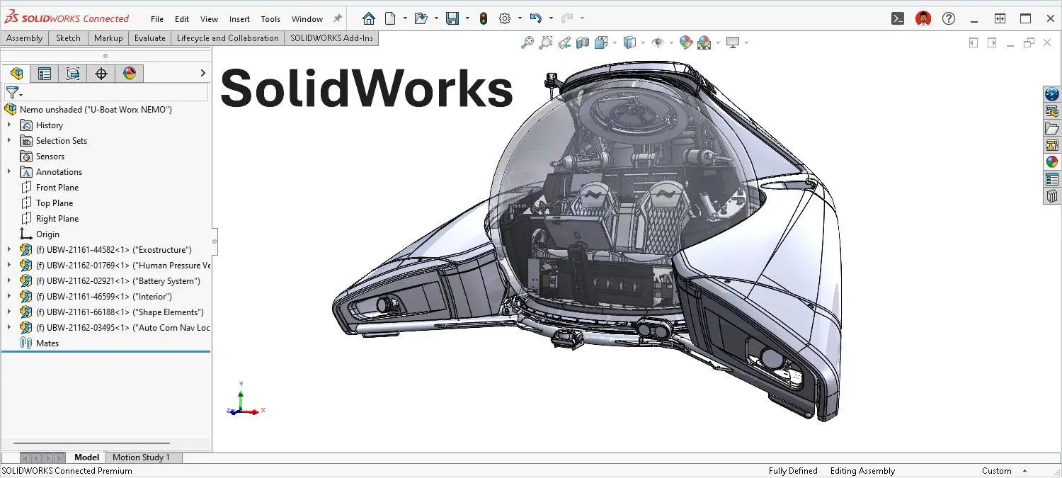
Introduction to SolidWorks and Interoperability
SolidWorks is a Computer-Aided Design (CAD) software developed by Dassault Systèmes, renowned for its ease of use and powerful 2D and 3D modeling capabilities. This system allows engineers and designers to create precise models, complex assemblies, and detailed technical drawings.
CAD data interoperability is a major challenge for companies using SolidWorks, particularly in a multi-CAD collaboration context where different partners, suppliers, and customers may be working with different CAD systems. The ability to reliably and accurately exchange data between these systems is essential for maintaining design integrity and optimizing product development processes.
History and Evolution of SolidWorks
SolidWorks was founded in December 1993 by MIT graduate Jon Hirschtick, who invested $1 million won playing blackjack to fund this project. His vision was to create accessible and affordable 3D CAD software for engineers and designers, running on the Windows platform, which was gaining popularity at the time.
In 1995, the first version of the software, SolidWorks 95, was launched, marking a revolution in the democratization of 3D design. It was the first 3D CAD tool capable of running on a standard desktop PC. Its intuitive interface, robust modeling capabilities, and affordable price quickly attracted the attention of the engineering and design communities.
On July 25, 1997, Dassault Systèmes acquired SolidWorks for $310 million, becoming the largest shareholder and continuing its development to this day. This acquisition by a world leader in CAD and PLM marked the beginning of a new chapter for SolidWorks, benefiting from Dassault Systèmes' extensive resources and global reach.
In the early 2000s, SolidWorks continued to innovate by introducing new features such as as well as web-based collaboration tools and enhanced simulation capabilities. These tools allowed designers to test and refine their models in the same environment.
Today, SolidWorks is used by approximately 7 million engineers and designers worldwide (2023 figures), primarily in the fields of industrial equipment, high technology, life sciences, housing, architecture, engineering, and construction.
SolidWorks File Formats and Extensions
SolidWorks uses several native file formats to store different types of CAD data:
SolidWorks Native Formats:
- .sldprt: Part File SolidWorks
- .sldasm: SolidWorks assembly file
- .slddrw: SolidWorks drawing file
- .slddrt: SolidWorks Template File
These native formats allow you to preserve all parametric information, build history, and design intent created in SolidWorks.
SolidWorks Import and Export Capabilities
SolidWorks offers extensive import and export capabilities through the use of Spatial's InterOp 3D CAD data exchange and interoperability software. This technology allows SolidWorks to support more than 30 neutral and proprietary CAD/CAM file formats.
Table of supported formats by SolidWorks
| Category | Format | Extension | Import | Export | Supported version |
|---|---|---|---|---|---|
| SolidWorks Native Formats | SolidWorks Part | .sldprt | - | - | All versions |
| SolidWorks Assembly | .sldasm | - | - | All versions | |
| SolidWorks Drawing | .slddrw | - | - | All versions | |
| Standard exchange formats | STEP | .stp, .step | ✓ | ✓ | AP203/214 |
| IGES | .igs, .iges | ✓ | ✓ | Version 5.3 | |
| Parasolid | .x_t, .x_b | ✓ | ✓ | Until V32 | |
| ACIS | .sat | ✓ | ✓ | Until R22 | |
| VDAFS | .vda | ✓ | ✓ | Version 2 | |
| Third-party CAD formats | CATIA V5 | - | ✓ | ✗ | Up to V5R27 |
| CATIA Graphics | .cgr | ✓ | ✓ | Up to V5R24 | |
| Pro/E / Creo Part | .prt | ✓ | ✓ | Import up to Creo 8.0, export up to Version 20 | |
| Pro/E / Creo Assembly | .asm | ✓ | ✓ | Import up to Creo 8.0, export up to Version 20 | |
| NX / Unigraphics | .prt | ✓ | ✗ | Version 10 and above, including NX 9 | |
| Inventor Part | .ipt | ✓ | ✗ | Version 11 and higher | |
| Inventor Assembly | .iam | ✓ | ✗ | Version 11 and higher | |
| Solid Edge Part | .par, .psm | ✓ | ✗ | Up to Solid Edge with Synchronous Technology 6 | |
| Solid Edge Assembly | .asm | ✓ | ✗ | Up to Solid Edge with Synchronous Technology 6 | |
| Rhino | .3dm | ✓ | ✗ | Version 4 | |
| CADKey | .prt, .ckd | ✓ | ✗ | Version 19 (prt), Version 21 (ckd) and higher | |
| Formats 2D | AutoCAD Drawing | .dwg | ✓ | ✓ | AutoCAD 2013-2015 (import), AutoCAD 2013 (export) |
| Drawing Exchange Format | .dxf | ✓ | ✓ | AutoCAD 2013-2015 (import), AutoCAD 2013 (export) | |
| Adobe Illustrator | .ai | ✓ | ✗ | - | |
| Mesh formats and 3D printing | STL | .stl | ✓ | ✓ | Version 1 |
| VRML | .wrl | ✓ | ✓ | Up to VRML 2 (VRML 97) | |
| PLY | .ply | ✓ | ✓ | - | |
| Point Cloud | - | ✓ | ✗ | - | |
| Viewing formats and collaboration | 3D XML | .3dxml | ✗ | ✓ | Version 4.2 |
| HOOPS | .hsf | ✗ | ✓ | Version 18.16 | |
| Highly Compressed Graphics | .hcg | ✗ | ✓ | CATIA V5 R9 | |
| IFC (BIM) | .ifc | ✓ | ✓ | IFC2X3 |
SolidWorks MBD and PMI interoperability capabilities
SolidWorks Model Based Definition (MBD) is an add-on that significantly expands SolidWorks' interoperability capabilities, particularly with regard to support for the STEP AP242 format. This module allows you to move from a product definition based on traditional 2D drawings to a fully 3D approach that integrates all manufacturing information directly into the model.
Support for the STEP AP242 format
The STEP AP242 format represents a major evolution in CAD interoperability, combining the features of the AP203 and AP214 formats while adding support for PMI (Product Manufacturing Information). These PMIs include dimensions, geometric tolerances, surface finishes, weld symbols, and other technical annotations directly integrated into the 3D model.
STEP AP242 Export Capabilities:
- Available since SolidWorks 2017 with the MBD module
- Accessible via the "Publish STEP 242 File" command in the MBD tab of the Command Manager
- Allows you to export all 3D and PMI annotations with the geometric model
- Includes the ability to export custom model properties
Specific Export Settings:
- Option to split periodic faces (such as cylindrical faces) to improve export quality
- Ability to export face properties and Edges to preserve important model geometry information
- Control over custom properties to include in the STEP AP242 file
STEP AP242 Import Capabilities:
- Direct import of STEP AP242 files is now supported in recent versions of SolidWorks
- Imported models retain their solid structure, as confirmed by comparative studies between different CAD systems
Benefits of the MBD approach with STEP AP242
Using SolidWorks MBD with the STEP AP242 format offers several significant advantages:
- Elimination of 2D drawings: No need to send both 2D drawings and 3D CAD data to manufacturers, simplifying management Documentation
- Time Saving: Particularly beneficial for complex models with many PMIs
- Reduced Interpretation Errors: Manufacturing information is directly linked to the relevant geometric elements
- Better Interoperability: The STEP AP242 format is considered the best STEP format to use because it is compatible with MBD/MBE (Model-Based Enterprise) workflows
- Universal Viewing: STEP AP242 files can be viewed in eDrawings, allowing partners without SolidWorks to view models with their PMIs
Workflow Integration
SolidWorks MBD integrates seamlessly into existing workflows :
- Step AP242 files can be attached to eDrawings files when publishing, allowing both the lightweight visualization and the complete geometric data to be shared.
- Users can view, extract, or delete STEP attachments directly from eDrawings.
- The MBD module also allows publishing to other formats such as 3D PDF, facilitating information sharing with partners without CAD tools.
The adoption of SolidWorks MBD with STEP AP242 support represents an important step towards the Model-Based Enterprise (MBE), where the 3D model becomes the primary reference for all stages of the product lifecycle.
Advanced Interoperability Technologies in SolidWorks
SolidWorks integrates several advanced technologies to improve the interoperability of CAD data, enabling engineers and designers to collaborate effectively in multi-CAD environments. These sophisticated tools address the complex challenges of exchanging technical data while preserving model integrity.
SOLIDWORKS 3D Interconnect
Introduced in 2017, 3D Interconnect represents a major evolution in SolidWorks' interoperability strategy, replacing legacy conversion capabilities. This technology fundamentally transforms the way users work with third-party CAD data.
Key Features:
- Directly opens native third-party CAD formats (CATIA, NX, Inventor, Creo, Solid Edge) without prior conversion
- Imports proprietary data directly into a SolidWorks assembly while preserving relationships
- Automatically updates the SolidWorks file when the original data changes, maintaining synchronization between systems
- Option to break the link with the imported file to create an independent copy if necessary
- Preserves important metadata such as custom properties and attributes
Workflow Benefits:
- Significantly reduces the time spent on file conversion
- Reduces translation errors Geometric
- Maintains association with source files, enabling dynamic updates
- Simplifies collaboration processes with partners using other CAD systems
3D Interconnect supports many native formats, including CATIA V5 (up to V5-6 R2024), NX (up to NX 2406), Creo (up to Creo 11.0), Solid Edge, and Inventor (up to 2025), as confirmed by recent compatibility data.
3DEXPERIENCE Exchange
This technology bridges the gap between SolidWorks and Dassault Systèmes' 3DEXPERIENCE platform, creating a unified digital ecosystem for design, simulation, and product lifecycle management.
Key Capabilities :
- Two-way data synchronization between SolidWorks and the 3DEXPERIENCE platform
- Secure cloud-based design sharing with version control
- Access to the 3DEXPERIENCE platform's advanced collaborative tools
- Centralized management of technical data and engineering processes
This integration allows geographically dispersed teams to work simultaneously on the same projects, accelerating product development cycles.
ScanTo3D
ScanTo3D is an add-on to SolidWorks Premium that transforms scanned data into usable CAD models. This technology is essential for reverse engineering and integrating physical objects into the digital design workflow.
Conversion Process:
- Import of point clouds or meshes (PLY, STL formats, etc.)
- Cleaning and preparation of scanned data
- Automatic recognition of geometric features
- Creation of NURBS surfaces or parametric solids
- Integration into the SolidWorks construction tree
Practical Applications:
- Reverse engineering of existing parts whose drawings are unavailable
- Product customization based on organic or sculpted shapes
- Digitizing physical objects for integration into designs Digital Quality Control
- Quality Control by Comparing Manufactured Parts to Original CAD Models
ScanTo3D supports various mesh formats, including STL, VRML, PLY, and point clouds, providing maximum flexibility for importing scanned data.
2D to 3D Conversion
SolidWorks offers powerful tools for transforming 2D technical drawings into parametric 3D models, allowing you to modernize older designs and capitalize on existing technical archives.
Available Conversion Methods:
- Import DWG/DXF drawings and extrude profiles
- Automatic view recognition and 3D reconstruction
- Dimension interpretation to create parametric models
- Conversion of annotations into 3D PMI (Product Manufacturing Information)
Business benefits:
- Leverage existing 2D technical archives
- Reduced re-modeling time
- Improved accuracy compared to manual reconstruction
- Facilitates the transition to fully 3D design processes
SolidWorks Diagnostic and Repair Tools
SolidWorks integrates sophisticated tools to diagnose and repair geometric problems during file import, ensuring model integrity throughout the process. exchange.
Import Diagnostics:
This tool systematically analyzes imported files to identify various geometric anomalies:
- Missing or degenerate surfaces
- Unconnected or redundant edges
- Unstitched faces or faces with holes
- Self-intersecting geometries
- Continuity issues between surfaces
The diagnostics generates a detailed report of the detected problems and offers various repair options, allowing users to choose the most appropriate method depending on the context.
Visual Properties Import:
SolidWorks preserves the visual attributes of imported models:
- Surface colors and textures
- Surface properties Materials
- Finishes and Special Effects
- Lighting and Environment Settings
This feature is particularly important for teams working on the aesthetic appearance of products, such as in the industrial design or consumer goods sectors.
Geometric Healing:
The automatic healing process corrects various geometric imperfections:
- Closing small gaps between surfaces
- Correcting degenerate faces
- Eliminating redundant edges
- Adjusting surface normals
- Repairing topology issues
These diagnostic and repair tools are essential for maintaining CAD data quality when exchanging data between disparate systems, thus reducing costly errors in the subsequent product development.
SolidWorks Interoperability Best Practices
To optimize SolidWorks data interoperability, here are some recommendations:
- Use standardized neutral formats: For exchanges between different CAD systems, favor STEP or Parasolid formats, which better preserve geometry.
- Import Preferred Order: For best results, follow this order: Parasolid (.x_t) > STEP (.stp) > ACIS (.sat) > IGES (.igs).
- Post-Import Checking: Always check models after import to detect possible errors or data loss.
- Simplification Prerequisite: Simplify complex models before export to reduce the risk of errors during conversion.
- Metadata Documentation: Clearly document important metadata (materials, tolerances, etc.) that may not be properly transferred during exchange.
- Using 3D Interconnect: For frequent collaborations with users of other CAD systems, consider using 3D Interconnect over full conversion.
CAD Interop Solutions for SolidWorks
CAD Interop distributes several specialized solutions to improve the interoperability of SolidWorks data, each addressing specific needs in the engineering data lifecycle. These complementary tools enable companies using SolidWorks to maximize the value of their CAD data by facilitating its sharing, validation, and reuse in different contexts.
3DViewStation 2025: View and Analyze Your SolidWorks Models Without a CAD License
3DViewStation is a high-performance visualization and analysis solution that allows you to examine SolidWorks CAD models without requiring a full SolidWorks license. This solution is particularly well-suited for sharing models with collaborators who don't need to modify the files.
Key Capabilities:
- Supports SolidWorks files from 1997 to version 2024
- Fast visualization even for complex assemblies thanks to advanced optimization algorithms
- Accurate measurement, sectioning, and analysis tools
- Create exploded views and animations
- Generate technical documentation with annotated screenshots
- Available in Desktop and WebViewer versions for maximum accessibility
3DViewStation also offers export capabilities to various formats, allowing you to convert SolidWorks data into neutral formats such as STEP, JT, and 3D PDF, or visualization formats such as FBX and glTF.
CADfix 2025: Repair and Simplification Solution for SolidWorks Files
CADfix is a powerful SolidWorks data repair and simplification tool that can correct complex geometric problems. It allows you to prepare models for various downstream applications and optimize data for FEA analysis, CAM, or 3D printing.
Key Features:
- Support for SolidWorks files from version 98 to 2025 via Parasolid
- Automatic diagnosis and repair of geometric problems (missing faces, unconnected edges, etc.)
- Model simplification while preserving essential features
- Defeaturing tools to remove irrelevant details depending on the context of use
- Conversion between B-rep and mesh representations
- Specific preparation for simulation, manufacturing, or long-term archiving
CADfix is particularly useful in multi-CAD environments where SolidWorks models must be shared with partners using other CAD systems, as it helps eliminate interoperability issues before they arise.
CADIQ 2025: Advanced Validation and SolidWorks Model Comparison
CADIQ is a validation solution that allows you to verify the integrity of SolidWorks models in exchange processes and accurately document changes (ECO). This solution detects subtle issues that could affect manufacturing or assembly.
Validation Capabilities:
- Support for SolidWorks versions 2022 to 2024 with the SolidWorks API
- Detection of over 180 types of potential defects in models
- Analysis of PMI (Product Manufacturing Information) and annotations
- Precise comparison between versions of the same model to identify changes
- Generation of detailed reports in 3D PDF or HTML format
- Possible integration with PLM systems via a command-line interface
CADIQ 16.5.1 offers advanced features such as analysis of imported visual properties, validation of geometric tolerances, and verification of compliance with standards enterprise.
DEXcenter 2025: Secure Automation of SolidWorks Data Exchange
DEXcenter is a CAD data exchange automation platform that facilitates collaboration between teams using different CAD systems. It offers a secure and scalable enterprise portal to manage data exchanges, including CAD conversions, between suppliers and customers.
Key Features:
- Web interface accessible via a standard browser
- Secure environment with data encryption during transfer
- Detailed record of each exchange for traceability
- Automatic generation of 2D and 3D Technical Data Packages (TDPs)
- Automatic validation of 3D TDPs including PMI
- Possible integration with existing PLM systems
- Compliance with international regulations (ITAR)
DEXcenter enables t automate exchange processes that would otherwise be manual and error-prone, while maintaining a high level of security and traceability.
Proficiency 2025: Parametric Conversion of SolidWorks Models with History
Proficiency is a specialized solution for converting SolidWorks models while preserving their build history (parametric conversion) as part of CAD migrations or multi-CAD collaborations.
Solution Architecture:
- Collaboration Gateway: Server for task creation and centralized reporting
- Proficiency Agent: Application that integrates with APIs CAD systems
- DrawtoPMI: Module for converting 3D models and 2D drawings into annotated 3D MBD files
- Completion Wizard: Plugin for manual remastering after automated exchange
Elements preserved during conversion:
- Exact geometry
- Complex features and structures
- Build history
- Sketch relationships
- PMI manufacturing information
- Metadata
- Assembly information
- Associated drawings
This solution is particularly valuable when migrating from SolidWorks to other CAD systems or vice versa, because It preserves design intelligence that would be lost with traditional conversion methods.
SimLab 2025: Create Immersive VR/AR Experiences from Your SolidWorks Models
SimLab is an innovative solution for creating immersive experiences from SolidWorks models, transforming designs into interactive visualizations for training, marketing, or design review.
Key Features:
- Direct conversion of SolidWorks models into virtual or augmented reality experiences
- Support for 18 input and 15 output file formats
- Preservation of animations, materials, and textures during Conversion
- Creation of interactive experiences without programming using the Training Builder tool
- Development of quizzes and assessment criteria in a VR environment
- Compatibility with LMS (Learning Management Systems) via XAPI and SCORM
- Cloud sharing and real-time collaboration features
Practical applications for SolidWorks users:
- Creation of interactive training manuals for complex products
- Development of immersive sales presentations for customers
- Implementation of collaborative design reviews in virtual reality
- Simulation of assembly or maintenance procedures
- Creation of innovative marketing experiences for trade shows
SimLab offers various Subscription plans tailored to the needs of businesses and educational institutions, with specific licenses for educational labs (Lab License and Lab License Pro) including VR collaboration capabilities for up to 30 participants per session.
This solution radically transforms the way SolidWorks data can be leveraged beyond engineering design, enabling its use in training, marketing, and immersive collaboration contexts, without requiring programming skills.
Conclusion
CAD data interoperability is a critical issue for SolidWorks users working in multi-CAD environments. With its native import/export capabilities, advanced technologies like 3D Interconnect, and an ecosystem of specialized solutions like those offered by CAD Interop, SolidWorks offers robust options for addressing interoperability challenges.
By following data exchange best practices and using the right tools, companies can optimize their collaboration processes, reduce conversion errors, and maintain the integrity of their designs throughout the product development cycle.
For more information on CAD interoperability solutions for SolidWorks, please contact CAD Interop, a specialist in CAD data interoperability and distributor of software for converting, visualizing, controlling, and simplifying 3D and 2D data.